Integrated temperature sensor
Onboard room-temperature monitoring on every CAN keypad, no extra sensor needed for basic monitoring.


SmartAPEX wired room control APX-CA · APX-CD
One shared back-unit platform, wired for AC or DC. One faceplate choice on top: Crystal glass or Classic metal — the same control concept, a different finish for the room.
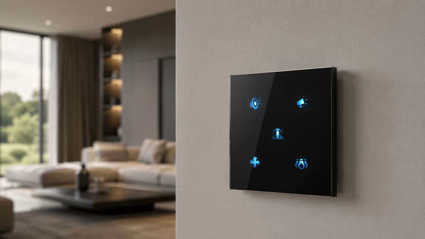 Crystal glass · 5-button layout shown
One electronic platform
Every keypad is built from two parts. The back-unit is the part that goes into the wall box and decides how the keypad is powered and wired. The faceplate is what the room sees — and it doesn’t change the control logic underneath.
Finish gallery
Two faceplate families, each in a set of finishes. Photos show one finish per family — the dots below mark every colour the family ships in.
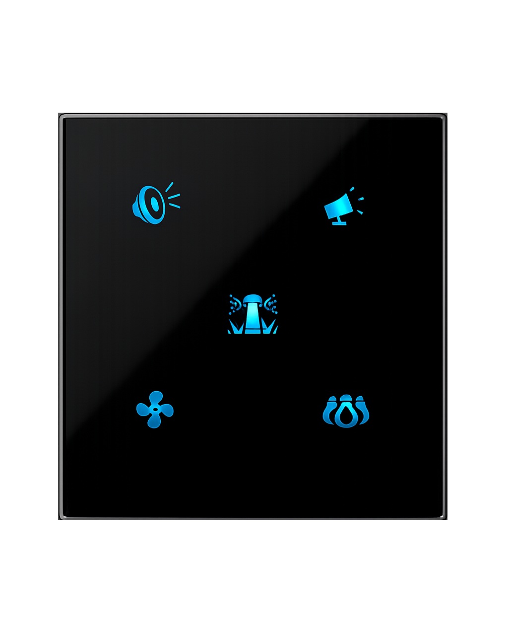
Glass faceplate, 1 to 5 predefined touch layouts.
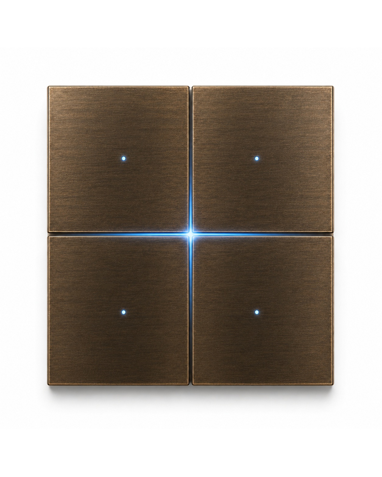
Metal faceplate, fixed 4-button layout.
Keypad intelligence
Regardless of finish or back-unit, every SmartAPEX CAN keypad shares the same six capabilities.
Onboard room-temperature monitoring on every CAN keypad, no extra sensor needed for basic monitoring.
Use onboard sensing, or switch to a compatible external NTC/IR probe by configuration.
Serviced through a compatible SmartAPEX CAN controller or service tool — no faceplate removal required.
Short press, long press, double-click and triple-click can each trigger a separate project action on the same touch position.
On the 5-button glass layout, the centre touch point is a logical CAN/scene input — not a fifth relay output.
Interlocked, break-before-make direction outputs — the two directions are never energised together.
 Evening
 Night Mode
 Reading
 Cooking
 Curtains
Configurable icon presentation
Personalization at your fingertips: icons, blanks and diffusers are matched to the selected button layout, with alternative icons available via the SmartAPEX icon-selection sheet before ordering.
Configurable, not fixed: icon backlight isn’t tied to one colour — each position can be set to any of the keypad’s supported colours after installation.


The physical touch map and available electrical outputs still depend on the selected faceplate layout and back-unit. Icon selection changes the interface, not the electrical rating.
Glass faceplate options
Crystal glass supports five predefined touch layouts. Metal faceplates always use the fixed 4-button arrangement shown separately above.
Diagram shows one glass panel with up to five touch zones — not four separate switch caps. The fixed 4-button metal faceplate is a different physical part, shown in the finish gallery above.
Back-unit specifications
Select the back-unit from the project’s electrical requirements first, then specify the Crystal or Classic faceplate on top. AC and DC versions have different terminals and electrical capabilities.
Mains-powered installations requiring local switched outputs alongside CAN-bus communication.
Low-voltage room interfaces using dry-contact inputs and a compatible external temperature or IR probe.
Electrical installation and load selection must follow the exact product manual and be completed by a qualified professional. Full wiring diagrams for both versions are in the manual, not reproduced here.
Installation
Isolate power before wiring, servicing or changing the faceplate. Follow the exact AC or DC wiring page in the manual.
Glass faceplate kit
Product overview
Product manual
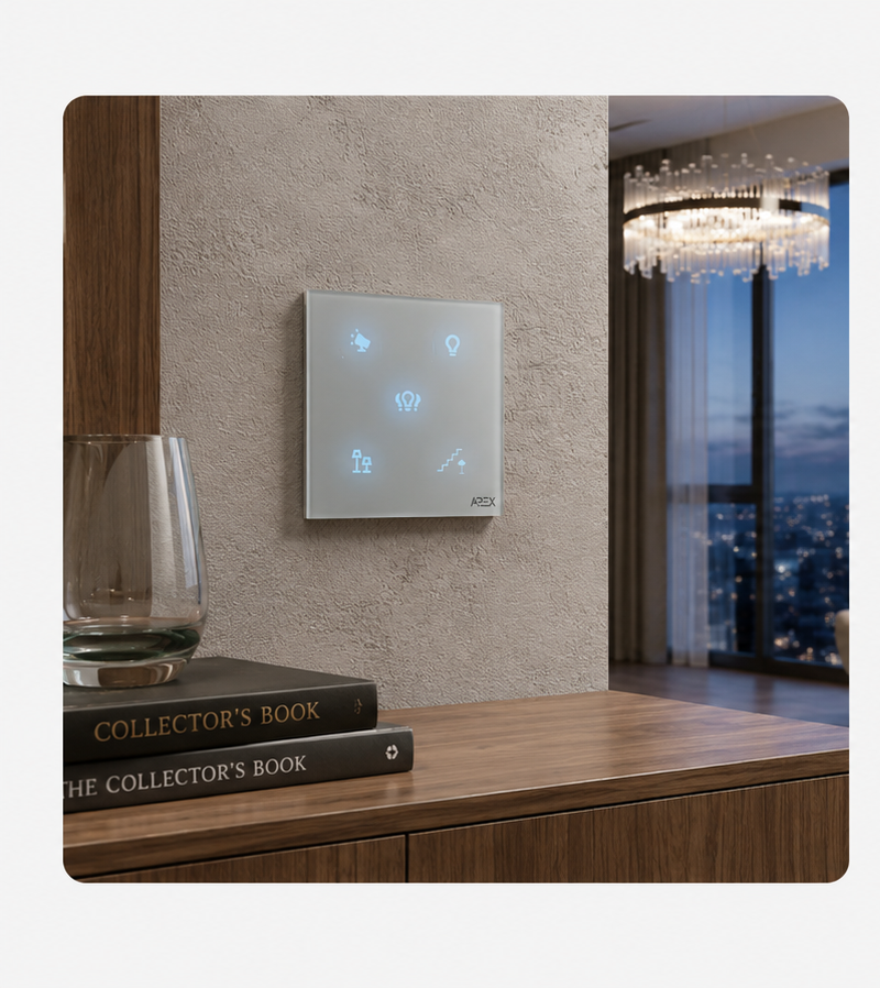
The manual covers Crystal and Classic faceplate preparation, CAN-bus back-unit wiring diagrams for AC and DC versions, temperature sensing, curtain safety and technical limits — the authoritative source for anything electrical.
We use only the cookies this site needs to work. With your agreement we also load Google reCAPTCHA, which protects our forms from spam and sets its own cookies. Read the cookie policy.