

SmartAPEX DIN-Rail automation node APX-DG
DALI Gateway
DIN-rail DALI master for Ethernet-based lighting control. Commission DT6 and DT8 gear from a web interface, then bind SmartAPEX CAN-BUS devices to DALI addresses, groups and scenes.
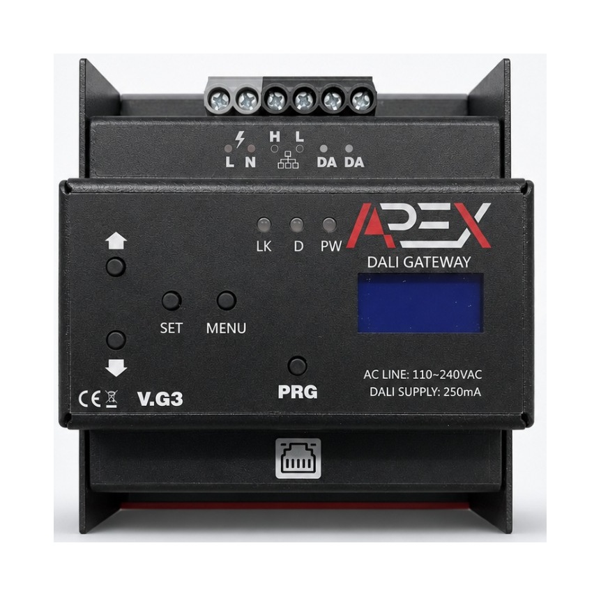 Manual render shown · real studio photo pending
DALI short addresses
DALI groups
DALI scenes
Integrated DALI supply
Installation-ready highlights
Everything an installer needs for one DALI line.
DALI Commissioning
Read-only rescan, safe addressing of unaddressed gear and explicit full readdressing.
Web Configuration
Network setup, device labels, groups, scenes, diagnostics and firmware workflows.
SmartAPEX CAN Bus
Discover compatible CAN devices and bind them to DALI addresses, groups or scenes.
DT8 Color Control
DT6 plus DT8 tunable white, XY, RGB, RGBW and RGBWAF control where supported.
Product overview
A compact DALI master for Ethernet-based lighting control.
Commissioning, device control, groups, scenes, network settings and firmware maintenance all run from one web interface.
DALI Master
Up to 64 short addresses, 16 groups and 16 scenes with DT6 and DT8 support.
Integration
Ethernet web interface plus SmartAPEX CAN device discovery, configuration and bindings.
DIN-Rail
Designed for cabinet installation. Follow the approved wiring drawing and local electrical rules.
System architecture
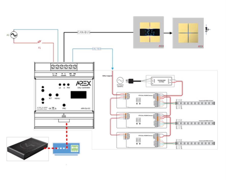
DALI line, CAN bus and Ethernet meet at one gateway.
The gateway connects the DALI lighting line to Ethernet and CAN bus. The web interface is used for commissioning, device control, groups, scenes, network settings and firmware maintenance.
| Terminal group | Function |
|---|---|
| L / N | AC line supply |
| H / L | CAN bus high / low |
| DA / DA | DALI bus pair |
Safety before power-up
- Installation and commissioning must be performed by a qualified installer.
- Isolate power before wiring or changing DALI, CAN or mains connections.
- Keep the gateway and DALI gear powered during addressing and firmware update.
- Do not disconnect the DALI line while commissioning is active.
Gateway status indicators
Read link, traffic and power state at a glance.
LK reports Ethernet link and host state. D flashes on message traffic. PW shows network acquisition progress through its blink rate.
| LED | State | Meaning |
|---|---|---|
| LK | Red | Ethernet not connected. |
| LK | Green | Ethernet connected; acquiring a DHCP IP address. |
| LK | Yellow | Ethernet connected, DHCP IP acquired and connected to the host. |
| LK | Blue | Ethernet connected and using a static IP address. |
| LK | Purple | Ethernet connected, using a static IP address and connected to the host. |
| D | Activity | Transmission and reception of messages via Ethernet or CAN bus. |
| PW | Fast blinking | Not connected to the network. |
| PW | Slow blinking | Ethernet cable connected; attempting to obtain an IP address. |
| PW | Very slow blinking | Module connected to the network with a valid IP address. |
Diagnostic reading. If PW is fast blinking, check the Ethernet cable and link. If it is slow blinking, wait for DHCP. Very slow blinking means a valid network address has been obtained.
DALI commissioning
Choose the least destructive action.
Match the action to the installation state — from a safe read-only scan to a full address rebuild.
Rescan Existing Devices
Read-only scan of DALI short addresses 0 through 63. It does not send INITIALISE, RANDOMISE or PROGRAM SHORT ADDRESS commands.
Address Unaddressed
Commission only gear without a valid short address. Existing valid short addresses are preserved.
Full Readdress
Clears and rebuilds the DALI short-address plan. Use only for a new line or an intentionally discarded address plan.
Cancel Addressing
Requests a controlled stop. Wait for the gateway to report canceled or failed before taking further action.
Physical address maintenance
- Delete removes a row from the gateway’s local list only — it does not clear the physical driver address.
- Clear Physical Address changes the physical DALI gear and accepts an address from 0 through 63. After a successful clear, run Address Unaddressed to assign a new one.
- A duplicate-address warning can indicate overlapping DALI replies or a bus collision — isolate sections and rescan.
| Feature | Range | Use |
|---|---|---|
| Groups | 0–15 | Add or remove devices; labels are gateway metadata. |
| Scenes | 0–15 | Store and recall levels or DT8 values for a device or group. |
| Report | Line-wide view | Review memberships and stored scene information. |
Control & integration
Local control today, distributed control over CAN bus.
Use the web interface for local commissioning and connect compatible SmartAPEX CAN devices for distributed control.
| Control area | Available control | Notes |
|---|---|---|
| All Devices | Broadcast control | Applies the selected action across the DALI line. |
| Individual device | On, off, level | Targets one DALI short address. |
| DT8 colour | TC, XY, RGB, RGBW, RGBWAF | Shown according to the reported device type. |
| Groups / scenes | Membership, store, recall | Use after the addressing plan is stable. |
| Startup | Last state / normal | Verify on each approved driver model. |
Preserve previous state. When Last state is selected, the gateway programs and verifies SYSTEM FAILURE LEVEL = FF and POWER ON LEVEL = FF. The physical DALI driver is responsible for preserve behavior — the gateway does not replay a cached brightness level during recovery. Test the gateway and driver mains power-cycle separately, and repeat for each approved driver model.
Discover
Search CAN Devices for a full discovery, then use Refresh to update the cached state.
Configure
Review Overview and open Configuration only for fields supported by the device firmware.
Bind
Create documented bindings to local DALI addresses, groups or scenes and verify after restart.
Specifications
Technical product specifications.
Initial installation
Wire it, power it, then commission from the browser.
Complete the physical installation first, then use the web interface to commission the DALI line.
Network access defaults
| Item | Factory default | Installer action |
|---|---|---|
| Address mode | DHCP enabled | Read the assigned address from the router or Finder. |
| Static IP | 192.168.1.150 | Use only when a static configuration is intentionally selected. |
| Netmask | 255.255.255.0 | Match the site network plan. |
| Gateway | 192.168.1.1 | Match the site router when static IP is used. |
| Credentials | admin / admin | Change the default password after first login. |
Product manual
Install and commission with the exact technical guide.
Covers specifications, LED status, DALI commissioning actions, control and integration, and installation wiring — the authoritative source for anything electrical, plus diagnostics and site-handover reference for installers.