

SmartAPEX DIN-Rail automation node APX-1616-RL · APX-2416-RL
DIN-Rail Relay Module
Multi-function relay module for lighting, curtain motor, fan-coil and valve control. Cabinet-ready, high channel density, local binding and integration-ready Ethernet / CAN-BUS workflows.
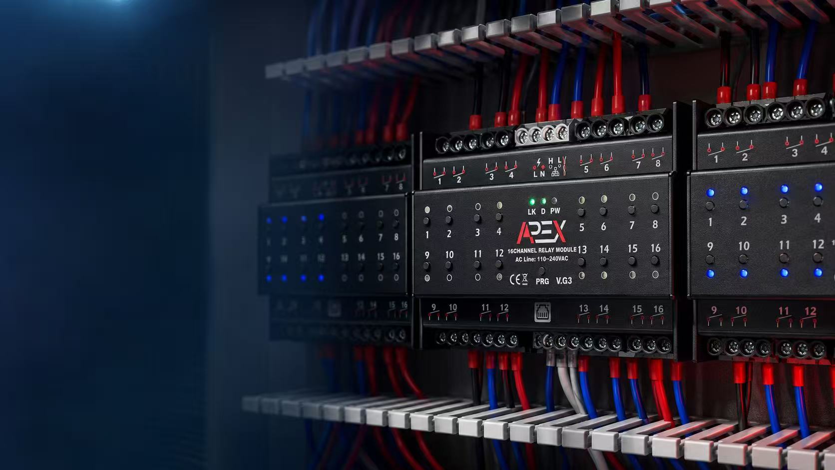 16-channel shown · installed in cabinet
Channel density
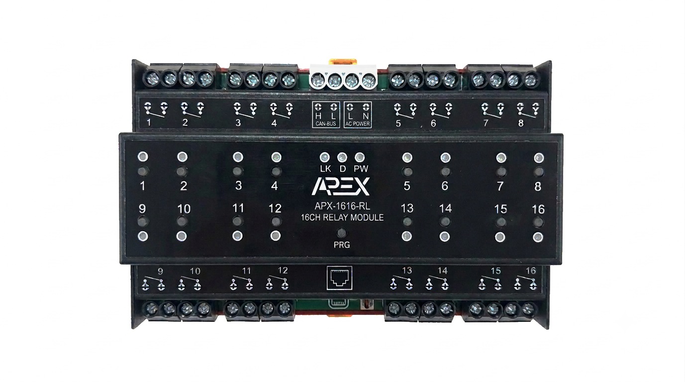
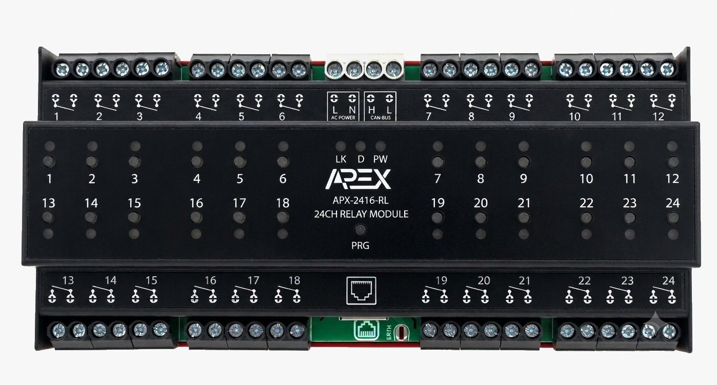
One module, two channel counts.
Same electrical ratings, same integration features on both — pick the density your panel needs.
Hardware highlights
Built for dense, serviceable cabinet installs.
Latching Relay Outputs
High-power latching relays per channel — hold their last state without continuous drive current.
Internal Power Supply
Built-in internal power supply — no separate external supply module needed to run the board.
Large, Convenient Terminals
Oversized wiring terminals sized for fast field wiring and easier cabinet servicing.
CAN-BUS Port Equipped
Dedicated CAN-BUS port for direct binding with keypads, thermostats and other DIN-rail nodes.
Metal Enclosure
Rigid metal body for durability and shielding in dense, high-channel-count cabinets.
Push-Button per Channel
A local push-button on every channel for manual override and testing without a controller.
SDDP Support
Built-in SDDP discovery for fast, plug-and-play commissioning on compatible systems.
Modbus TCP
Modbus TCP support is on the roadmap for a future firmware release, alongside Ethernet and CAN-BUS.
Product position
Not only a relay module — an integration-ready automation node.
The module combines relay outputs, manual override, per-channel feedback, Ethernet, CAN-BUS, SDDP and built-in web configuration into one DIN-rail platform.
Binding / Direct Control
Local CAN device-to-channel binding for keypad and automation workflows.
API for Integrators
Ethernet command, status, configuration and diagnostics for approved integrations.
SDDP Discovery
Fast discovery and easier commissioning in compatible automation systems.
Manual Override
Per-channel local push buttons and status indicators for service and testing.
Web Configuration
Built-in web setup for IP settings, channels, diagnostics and firmware workflows.
SmartAPEX CAN-BUS
Connect wall devices, keypads, thermostats, inputs and other DIN-rail modules.
Application map
One module, multiple cabinet roles.
Lighting
Incandescent, halogen, ELV/MLV, fluorescent, CFL and LED loads within derating limits.
Curtain motors
Motorized curtains and blinds using relay-pair logic where required. Motor ratings require project validation.
Fan coil
Three-speed fan coil and valve control configurations.
Valve / DC loads
Electrical valves and selected DC load control subject to voltage/current derating.
Specifications
Technical product specifications.
Electrical ratings are separated between product-level module limits and internal contact capability.
LED status
Commissioning indicators.
| LED | State | Meaning |
|---|---|---|
| LK | Red | Ethernet not connected. |
| LK | Green | Ethernet connected, acquiring DHCP IP. |
| LK | Yellow | Ethernet connected, acquired DHCP IP, and connected to the host. |
| LK | Blue | Ethernet connected, using STATIC IP. |
| LK | Purple | Ethernet connected, using STATIC IP, and connected to the host. |
| D | Activity | Transmission and reception of messages over Ethernet or CAN-BUS. |
| PW | Fast blink | Not connected to network. |
| PW | Slow blink | Ethernet cable connected, obtaining IP address. |
| PW | Very slow blink | Valid IP address and network connected. |
Local functions
Push-button commissioning and recovery.
- SDDP IdentifyPress and hold the PRG button for 4 seconds to initiate SDDP identification.
- Factory ResetPress and hold the PRG button for 12 seconds until the PW LED starts blinking fast. Release to reset to factory settings.
- Manual Static IPPress and hold the highest-numbered channel push button (16 or 24, depending on model) for about 15 seconds. When PW blinks rapidly, release — the module restarts at 192.168.1.150.
Binding and integration
Designed for panels, integrators and real projects.
Use the module as an Ethernet-connected cabinet controller, a SmartAPEX CAN-BUS node, or a bridge between wall devices and relay outputs.
Binding / Direct Connection
Local SmartAPEX device-to-device control can bind compatible CAN devices to relay targets. Typical use: keypad/input action → relay channel or relay group, with state feedback where supported. Binding capacity and supported object types depend on firmware version.
API for Integrators
Local API available for approved integrators. Capabilities include channel control, status monitoring, configuration access, diagnostics and binding workflows where supported. Final endpoint list depends on firmware version.
Browse to the module’s current IP address to open the built-in web configuration page. Network settings can be set for DHCP or static IP with the required IP, gateway and subnet parameters — the page may also expose channel configuration, scenes/schedules, firmware update and diagnostics depending on firmware version.
Product manual
Install and commission with the exact technical guide.
Each channel count has its own manual covering specifications, LED status, PRG functions, binding, integration and installation wiring — the authoritative source for anything electrical.